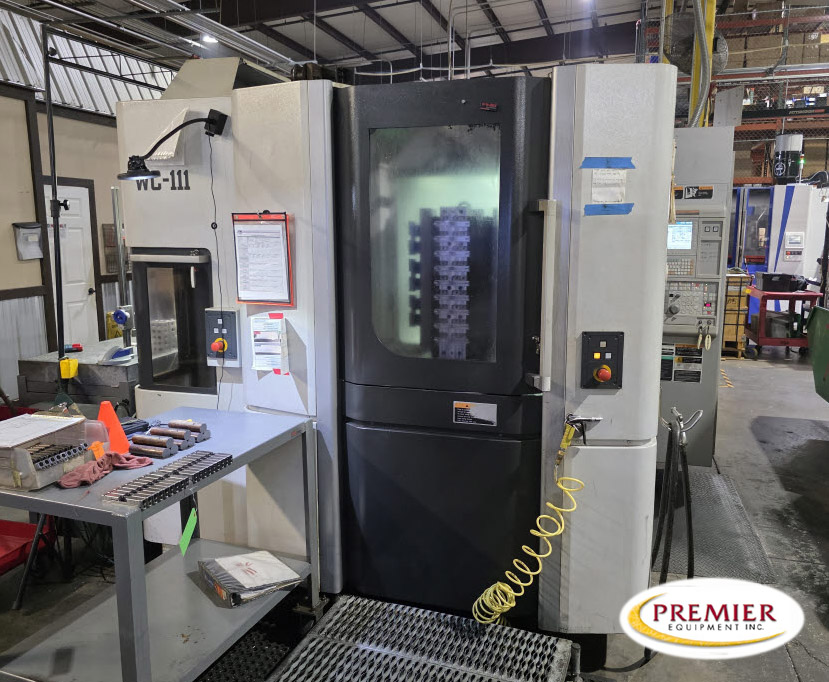

A casting can sit comfortably on a horizontal machining center’s pallet and still be wrong for the machine. Add the fixture, rotate the setup, bring a boring tool into the deepest feature, and the room you thought you had can disappear.
Horizontal machining center pallet size describes the mounting surface. It does not describe every part the spindle can reach, every fixture the B-axis can rotate or every load the pallet changer can carry. Those are separate limits.
The buying decision should start with the loaded setup and the operations it must complete. A pallet dimension is useful for sorting machines. It is not an application approval.
Read the capacity numbers as different measurements
An HMC specification sheet commonly separates pallet dimensions, axis travels, maximum workpiece size and payload. Each tells you something different about the proposed job.
The pallet gives the fixture a mounting surface and locating arrangement. Linear travels describe available machine motion. Maximum workpiece dimensions describe a stated envelope, often given as diameter and height. Payload describes a load limit under the manufacturer’s conditions. None of those numbers replaces the others.
Makino makes the distinction clear on its a51nx product page. Its current published metric specifications list a 400 x 400 mm pallet, a maximum workpiece of 630 mm diameter x 900 mm height, and a maximum payload of 400 kg. The page lists axis travels separately.
That example shows why a pallet width is neither the maximum part width nor the complete usable machining envelope. It does not mean every shape within those outer dimensions can be machined in every orientation. These figures apply to the published a51nx configuration, not automatically to an older machine with the same family name.
When comparing used horizontal machining centers, keep those separate measurements attached to the exact machine. A single capacity number is too easy to misread.
Draw the fixture before choosing the machine size
Start with the raw workpiece, not just the finished solid model. Cast stock, locating pads and machining allowance can extend beyond the final drawing. Then add the subplate, tombstone or angle fixture, locating hardware and every clamp that stays in place during cutting.
The assembled setup may be much taller than the part. A fixture that raises a casting to clear the pallet can move its upper features beyond useful spindle access. A thick subplate can consume height that looked available when the workpiece was sitting directly on the table in a sketch.
Clamps also occupy cutting space. A low-profile clamp may help a face mill reach one surface but block a drill approaching from another indexed position. The workholding design needs to support the cut and leave room for the complete tool assembly.
A fixture does not have to use every inch of the pallet to be a good fixture. Sometimes fewer parts or a narrower tombstone provides shorter tools and simpler access. That can be a better production plan than packing the pallet tightly and making every operation difficult.
Follow the full B-axis rotation
The outside corner of a rectangular setup sweeps a larger circle than its width suggests. Add a clamp projecting from one face or a casting mounted off-center, and the largest radius may be somewhere other than the feature that first caught your attention.
Model the rotation of the whole assembly around the actual B-axis center. Do not look only at the cutting positions. The setup must clear intervening angles during indexing, including the relationship to the spindle, enclosure and other fixed machine features.
A part may clear at two programmed orientations yet interfere while moving between them. The machine may also require a particular retract position before indexing. That movement belongs in the process, with adequate clearance for the installed tool and holder.
B-axis capability varies. A machine’s available indexing increments, contouring capability and rotary load restrictions come from its configuration. A specification saying the table rotates does not establish simultaneous four-axis cutting or unrestricted rotation with your loaded fixture.
For buying purposes, a rotating assembly model is much more persuasive than a statement that the part is smaller than the pallet. It exposes the space the job actually needs.
Tool reach can be the deciding limit
A tool tip reaching a feature is only part of the problem. The holder, spindle nose and adjacent fixture surfaces must clear throughout the approach, cut and withdrawal.
Long drills and boring tools need room between the spindle and the workpiece before entering the hole. A deep bore can consume Z-axis room through both part depth and tool projection. A large holder may interfere with a neighboring clamp even when the cutting edge reaches the correct coordinates.
Short tools raise a different question: can the spindle get close enough? A feature near the pallet or behind a fixture shoulder may require an approach the machine cannot make. Extra travel on a specification sheet does not necessarily fix that geometry.
Makino’s a51nx page also publishes maximum tool length, diameter and weight separately from workpiece capacity. That is a useful reminder that the automatic tool changer has its own limits. A tool that fits the machining space still has to suit the machine’s storage and exchange arrangement.
Keep the actual toolholder assemblies in the model. Replacing them with thin lines can hide the collision that decides whether the job fits. Clearance should remain practical through tool changes, probing and chip removal, rather than existing only at one cutting point.
Payload includes the workholding
The raw part does not get the entire payload allowance. The tombstone, subplate, vises, clamps and other carried equipment all contribute to the loaded assembly. Apply the OEM’s definition of payload and its stated conditions rather than assuming a catalog number refers only to the workpiece.
Weight distribution matters as well as total weight. A heavy casting on one face of a tombstone produces a different load condition from evenly distributed parts. The center of gravity, distance of mass from the rotary axis and height of the assembly can affect allowable operation.
Mass farther from the axis also changes rotational inertia. A setup that is under a static weight limit is not automatically acceptable for every indexing acceleration. Use the manufacturer’s permitted loading, moment and inertia conditions where supplied; unresolved conditions need an applications review.
A pallet may carry different loading states during a production cycle. One side could hold raw parts while another holds machined parts, or an operator could unload one face before loading another. The approved process has to account for those states. Do not invent a counterweight arrangement or a slower indexing workaround to get around an unsupported load condition.
The pallet changer needs clearance too
The machine has to move the loaded assembly into and out of the machining area. A setup that clears during cutting may still interfere at the transfer opening or loading station. Pallet storage adds another set of spaces and load conditions if the machine is connected to a pool.
Hydraulic connections can change fixture clearance. Mazak’s HCN NEO technical information distinguishes an optional hydraulic supply using hoses from above the pallet changer from an optional through-pallet supply. Mazak specifically describes reduced interference with the through-pallet arrangement.
That is a configuration detail with a direct consequence for fixture design. It is not a promise that every HCN, especially an older used machine, has either arrangement installed. The fixture drawing must reflect the connections on the machine being considered.
Loading access deserves the same attention. The operator needs a workable way to place the raw part, operate clamps and remove the finished piece. A layout that needs awkward handling on every cycle can undermine an otherwise sensible horizontal process.
Compare complete setups, not pallet classes
Consider a shop moving a family of valve bodies to an HMC. The compact body appears to fit a small pallet, but the proposed tombstone places several castings around its outside. The largest casting, its clamps and the boring tool may dictate the machine size. The smallest finished body does not.
There may be more than one workable answer. A narrower fixture with fewer parts might fit the smaller machine with good access. A larger machine might carry more parts per pallet but require a larger fixture investment. A different part orientation could improve the reach while changing the locating and clamping problem.
Those alternatives should be compared by accepted output, fixture cost and the operations completed, not by parts loaded alone. More pieces on the pallet do little good if long tools force slow cuts or a blocked feature sends every part back for another setup.
Premier’s Mazak HCN buying guide covers the broader production case for a used horizontal. For physical fit, bring the setup model and tool assemblies into the discussion before narrowing the search to a pallet class.
Include fixture development in the budget before discussing used CNC financing. An affordable machine with an unworkable fixture plan has not solved the capacity problem.
Talk with Premier Equipment about the part family, loaded setup and difficult operations. The useful starting point is the feature you cannot reach or the load you need to carry. That gives the machine comparison a clear purpose.
Frequently asked questions
Can a part be wider than an HMC pallet?
Yes, some machines allow a workpiece envelope wider than the mounting surface. The fixture must still provide proper support and remain within the machine’s documented workpiece, rotation, load and transfer limits. Overhang alone neither approves nor disqualifies the setup.
Does maximum workpiece diameter mean every feature is reachable?
No. A maximum workpiece envelope is not a guarantee of cutting access. Fixture placement, spindle approach, tool projection, holder clearance and axis limits determine whether the required operations can reach the features safely.
Does the pallet load rating include a tombstone?
Treat the tombstone and other carried workholding as part of the load, then confirm the OEM’s exact payload definition and conditions. Total weight is one constraint. Center of gravity, load distribution and rotary inertia may impose additional restrictions.
Can a bigger pallet solve a tool-clearance problem?
Sometimes a larger machine provides useful space, but pallet size alone does not establish that. The solution may be a different fixture orientation, shorter holder assembly or a machine with more suitable spindle access. Compare the complete machining and transfer motions before choosing.